I recently bumped into NodeMCU firmware for the ESP8266. It’s an Lua interpreter, making tinkering with IoT ideas really simple. Just flash the firmware onto the ESP8266 and connect via serial console. You can start prototyping right away using the interactive Lua interpreter. You can easily persist your ideas on a simple flash file system.
print(wifi.sta.getip())
--nil
wifi.setmode(wifi.STATION)
wifi.sta.config("SSID","password")
print(wifi.sta.getip())
--192.168.13.101
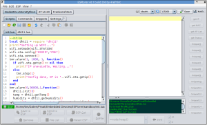
For convenient development, there is ESPlorer, a basic IDE for Lua on the NodeMCU. It allows you to develop the Lua scripts locally and then save them to the MCU via serial protocol.
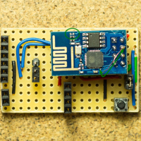
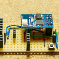
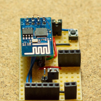
To make developing with the ESP-01 module easier, I created a basic development board. It provides easier access to the individual pins, has jumpers for flashing mode (GPIO00) and enable (CH_PD), offers a button for reset, and also integrates a socket for a step-down power supply.
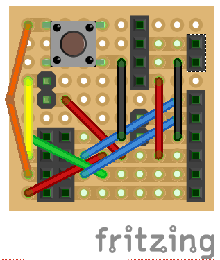
Although NodeMCU provides access to the deep-sleep mode of the ESP8266
node.dsleep(microSecs);
this is not available straight away on the ESP-01 module, as the ‘post-sleep-reset-pin’ XPD_DCDC (8) of the MCU is not connected to the reset pin. I solved this by manually soldering a single wire of a stranded cable between the reset pin of the module and the XPD_DCDC (8) pin of the MCU (bottom right corner of the mcu in the first photo). On top of this, I also removed the red power LED by simply prying it off with a tiny screw driver.
With these two modifications, the module is able to make use of the deep-sleep mode and successfully resets and restarts after waking.
During deep sleep the module now uses just 78 microAmps! On two normal AA batteries with 2600mAh, that’s good for well over 3 years!
Update 2015-04-12:
Due to frequent questions about the Fritzing file or schematics, I uploaded the Fritzing file:
ESP-01_ESP8266_Board.fzz
(if the file extension gets mixed up, apply .fzz manually)
Update 2015-11-18:
Marv Marvelous over at http://blog.grafovision.sk/ translated this article into Slovak. Thanks Marv!

hi
perfect job!
best wishes
rudi 😉
Hi!
Can you use interruptions to wake up the module when is in deel sleep mode? Or just with a timer?
Nice work!
Marcos
As far as I know, you can only use the timer. There was a comment about this on the hackaday post.
Amazing!!
Great Job!!!
It would be great if one version of ESP8266 would come with all pins on the site.
A combination of ESP-01 and ESP-03 would be perfect.
Breadboard friendly and more pins available so we we could focus more on development instead of making it work as it should.
Who’s in to start a petition for Espressif Systems to do it?
This one is pretty much like that: http://shop.in-circuit.de/product_info.php?cPath=21&products_id=67
It is really a great job. It would be superb if you make a YouTube video on this.
Tim, can you at least provide more details for you simple dev board for newbies? I’m really interested on it.
I’m sorry, I’m rather busy these days.
A few brief words: The board is just for convenience and not needed for the dsleep function. Dsleep just relies on that tiny wire between the reset pin and the XPD_DCDC pin.
I’ve noticed that system_deep_sleep_set_option has been added in the new SDK verison, my notes are here:
http://41j.com/blog/2015/01/esp8266-sleep-modes/
This disables wifi when the device wakes up. Could allow even lower power operation for applications when the device is periodically waking up to do data logging.
Hi… I have tried to get it into deep sleep for some time now.
When idle, it uses about 68mah
In deep sleep, i can’t get lower than 12mah.
Is my meter brooken, or am i missing something? – The “hack” with the wire to RST, is only if you want it to wake up right?
yea, the wire is just to reset after sleep… Any other components drawing current?
I just followed this guide, except for pulling off the LED. Only the wire seems to be needed. Pulling off the leds is only for saving the current for that. So you might want to leave the leds in place for developing purposes and only remove it if the module will be in the field.
Can you post the schematic of the board? The fritzing pic is so messy
I don’t have the time to look into schematics right now, but I uploaded the Fritzing file. Check the update at the end of the post.
I’m a bit puzzled; why isn’t the post-sleep-reset-pin connected to reset by default on the chip itself?
Good question, I suppose it’s a bit more flexible in its application this way?
Hi,
you can use the reset pin to wake up from deep sleep, not really an interrupted as the soc will reset the user program. The wake up signal pin can be used as gpio as well
This explains why the connection is not done in the chip.
What’s the capacitor under the ESP8266 for and what’s its value?
That’s to smoothen the power supply… I can look up the value when I get home…
Found you over Google. Nice work!
One question – if you put your ESP to sleep, does PWM still work?
– Set PWM to X%
– Set ESP to sleep
Is PWM still active at X%?
Good question 😉
I might give it a try and report here if I find out anything…
I’d like to use the ESP 8266 as a means to locate (using a cellphone with the WIFI Analyzer app) small things – i.e., just for maybe 30min after turning the chip on. The problem is that I need to use something like a CR1025 battery (10mm radius) to power it and I don’t think that battery has enough current capacity. If I could make it just activate for 2 minutes and then sleep for 1min – but how much added circuitry would that require. Any ideas? Thanks!
Dave
I cannot say this for sure, but I don’t think you would need any additional components. Apply the dsleep hack, program the module, pull CH_PD high, and apply the 3V power supply from the cell.
I did some testing in preparation for a battery powered application and found that it takes about 300ms to wake up from deep sleep. During that 300ms wakeup period, the ESP8266 consumes about 70ma, with short (10-20ms) spikes of up to 500ma. The 300 ms does not include any time needed to connect to a network.
For me, this means that deep sleep will not result in the kind of power savings I was looking for so that I could have a battery powered application report data every 2 seconds. It suggests that deep sleep will not result in substantial net power savings unless sleep is for an extended period. The current spikes also indicate that that the power source must be capable of supplying 500 ma for short periods. Alkaline batteries should work, but coin cells should not due to high internal resistance.
I am now going to check out other sleep modes not needing a full reset.
NB Measurements were made by placing 1ohm resistor in series with the power source and observing the voltage across the resistor on a scope. If you do this, be sure to isolate the grounds by using either a battery powered chip or a battery powered scope.
you may found this solution at
http://www.nrdcentre.com/wi-fi-toxic-gases-monitoring
Im’ wondering how what is your firmware because when i use nodemcu the current in deep sleep mode is 3mA (50 times more…)
Tried to solder wire to the MCU but abandoned it after fourth attempt. I’m struggling to see and attach wire. I twisted two small strands together and tinned the wire. Then tried to solder to MCU pin. It either wouldn’t fix or looked to solder two pins. If you have any tips it would be appreciated.
Two strands might be too much. I used a single strand of a stranded AWG22 wire. You will need really good light, good eyes, and a steady hand.
Are you certain this is just the module by itself? No other components which might draw additional current?
Nothing more.
On another ESP01, i have now deep sleep of 460µA
GPIO pullup or ADC have to be disabled? If yes, how does it possible that