My ESP-03 modules arrived

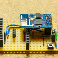
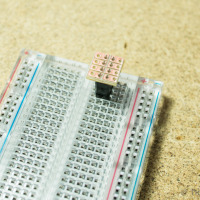
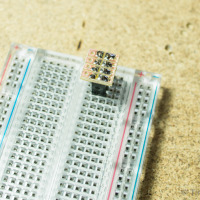
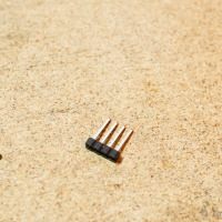
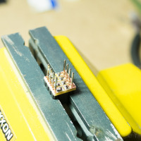
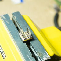
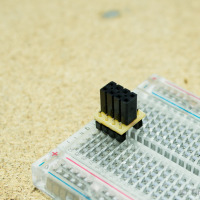
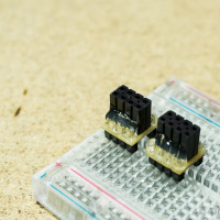
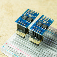
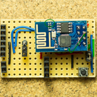
Today I received the ESP-03 modules I had ordered from Shanghai. A nice little breakout for the ESP8266EX with ceramic antenna. Due to the 2mm spacing between the contacts on the sides, I had to bend the headers into shape before soldering them to the module.

ESP-03 module for the ESP8266EX

As an initial function test I used the Bus Pirate in UART bridge mode to flash the latest NodeMCU firmware onto the chip.

Low Power ESP8266 – Sleeping at 78 micro Amps

I recently bumped into NodeMCU firmware for the ESP8266. It’s an Lua interpreter, making tinkering with IoT ideas really simple. Just flash the firmware onto the ESP8266 and connect via serial console. You can start prototyping right away using the interactive Lua interpreter. You can easily persist your ideas on a simple flash file system.

print(wifi.sta.getip())
--nil
wifi.setmode(wifi.STATION)
wifi.sta.config("SSID","password")
print(wifi.sta.getip())
--192.168.13.101

For convenient development, there is ESPlorer, a basic IDE for Lua on the NodeMCU. It allows you to develop the Lua scripts locally and then save them to the MCU via serial protocol.
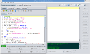
ESPlorer

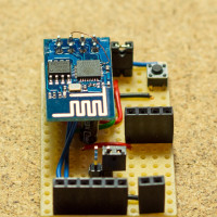
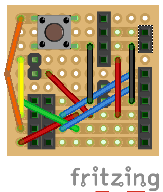
To make developing with the ESP-01 module easier, I created a basic development board. It provides easier access to the individual pins, has jumpers for flashing mode (GPIO00) and enable (CH_PD), offers a button for reset, and also integrates a socket for a step-down power supply.
ESP8266 (ESP-01) dev board top-view ESP8266 (ESP-01) dev board side-view
ESP8266 (ESP-01) dev board front-view ESP8266 Development Board

Although NodeMCU provides access to the deep-sleep mode of the ESP8266

node.dsleep(microSecs);

this is not available straight away on the ESP-01 module, as the ‘post-sleep-reset-pin’ XPD_DCDC (8) of the MCU is not connected to the reset pin. I solved this by manually soldering a single wire of a stranded cable between the reset pin of the module and the XPD_DCDC (8) pin of the MCU (bottom right corner of the mcu in the first photo). On top of this, I also removed the red power LED by simply prying it off with a tiny screw driver.
With these two modifications, the module is able to make use of the deep-sleep mode and successfully resets and restarts after waking.

During deep sleep the module now uses just 78 microAmps! On two normal AA batteries with 2600mAh, that’s good for well over 3 years!

Update 2015-04-12:

Due to frequent questions about the Fritzing file or schematics, I uploaded the Fritzing file:
ESP-01_ESP8266_Board.fzz
(if the file extension gets mixed up, apply .fzz manually)

Update 2015-11-18:

Marv Marvelous over at http://blog.grafovision.sk/ translated this article into Slovak. Thanks Marv!

DIY ESP8266EX Breadboard Adapter

Today I received the ESP8266EX Serial -> WiFi modules! After not being convinced by the rather expensive Adafruit TI CC3000 (35USD!) module I am now very curious about these tiny and cheap (<4USD) modules.

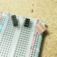
As their default header (2X4 male) is not exactly breadboard friendly, I sat down today and soldered a simple breadboard adapter. All you need is a tiny piece of stripboard 4×4, two male headers 1×4, two female headers 1×4 or one female header 2×4, and a bit of hot glue.

use the male headers to stbilise the female header place the strip-board on the female header solder the female header to the strip-board

  • Cut the stripboard to the correct size (4×4) and sandpaper any rough edges. Use a file to separate the copper strips across the middle.
  • Place the female header on a breadboard using the male headers to give it some stability and solder it to the stripboard. Watch out for the correct orientation!

re-aligned male header reverse inserted male headers solder the male headers

  • Re-align the plastic spacer of the male headers all the way to the top.
  • Place the stripboard with the male headers inserted from the non-copper side on some support (I used my vice for this).
  • Solder the male headers to the stripboard.

plastic spacer on the bottom side hot glue around the male header tips DIY breadboard adapter for the ESP8266

  • Now replace the plastic spacer of the male headers to the bottom side and push it as far up as possible (it probably will not go all the way because of the solder)
  • Add some hot glue around the tips of the male headers to provide additional support and strength.
  • Voilà!

The first tests using the Bus Pirate as UART bridge worked fine. I could talk to the module and connect to my home WiFi via WPA2.