DIY ESP8266EX Breadboard Adapter

Today I received the ESP8266EX Serial -> WiFi modules! After not being convinced by the rather expensive Adafruit TI CC3000 (35USD!) module I am now very curious about these tiny and cheap (<4USD) modules.

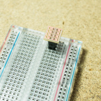
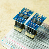
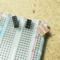
As their default header (2X4 male) is not exactly breadboard friendly, I sat down today and soldered a simple breadboard adapter. All you need is a tiny piece of stripboard 4×4, two male headers 1×4, two female headers 1×4 or one female header 2×4, and a bit of hot glue.

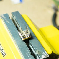
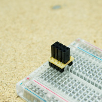
use the male headers to stbilise the female header place the strip-board on the female header solder the female header to the strip-board

  • Cut the stripboard to the correct size (4×4) and sandpaper any rough edges. Use a file to separate the copper strips across the middle.
  • Place the female header on a breadboard using the male headers to give it some stability and solder it to the stripboard. Watch out for the correct orientation!

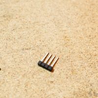
re-aligned male header reverse inserted male headers solder the male headers

  • Re-align the plastic spacer of the male headers all the way to the top.
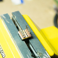
  • Place the stripboard with the male headers inserted from the non-copper side on some support (I used my vice for this).
  • Solder the male headers to the stripboard.

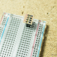
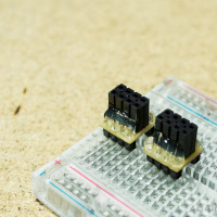
plastic spacer on the bottom side hot glue around the male header tips DIY breadboard adapter for the ESP8266

  • Now replace the plastic spacer of the male headers to the bottom side and push it as far up as possible (it probably will not go all the way because of the solder)
  • Add some hot glue around the tips of the male headers to provide additional support and strength.
  • Voilà!

The first tests using the Bus Pirate as UART bridge worked fine. I could talk to the module and connect to my home WiFi via WPA2.

EclipseCon Europe 2014

Last weeks EclipseCon Europe in Ludwigsburg, Germany was great! Thanks to all those active contributors, who made this event possible. Additional to the usual Java and Eclipse topics, there were very interesting sessions on the Internet of Things, web technologies, and OSGi.
It all started on Monday with a meeting by the Eclipse Science Working Group where things revolved around representations of scientific data and their visualisation. Key projects were the Eclipse Integrated Computational Environment (parallel visualisation), DAWNSci (data analysis), OpenChrom (chromatography), and OpenFlow (geology visualisation).

For a stream of conference photos, check out the flickr group.

The main conference began on Tuesday with a workshop on automated GUI testing based on Jubula. My personal highlights of the conference sessions on the following days were

  • ’10 platforms in 30 minutes’ where Jonas Helming live-coded 10 GUIs on different platforms based on EMF Forms. The paper print-out even got delivered by micro-quadrocopter! 😀
  • The presentation of openHAB (home automation bus) as the center of an Eclipse based SmartHome.
  • The keynote ‘Innovation Begins at Home’ by Andy Stanford-Clark who automated his home early on and created the Twittering Isle of Wight Ferries.
  • Ian Craggs providing an overview of the currently available embedded implementations of MQTT and MQTT-SN which just last week were accepted as OASIS standards.
  • A live demonstration of Docker providing a very flexible infrastructure for Eclipse RT applications. I recently had the chance to try out Docker and it is really amazing. If you are looking for a lightweight and highly flexible alternative to virtualization on Linux, try this!
  • Last but not least, Gordon Williams‘  and Tracy Miranda‘s introduction to the Espruino JavaScript embedded platform. It consists of an ARM based micro-controller running Gordon’s open source JavaScript interpreter and a web-based IDE. When Gordon integrated Espruino with the Eclipse Orion web-IDE, he could not access the serial port because of access rights limitations of the web-browser. As a work around he turned to generally available interface of web-applications, the audio out- and input! By adding a simple circuit and an orion plugin, he was actually able to use a normal audio jack as serial interface to the microcontroller! Now this totally reminds me of the Acoustic couplers of the good old days when the nets still made hissing sounds 🙂

All in all, with the great conference food, the entertainment with Circus Eclipse and the rock-band Cool Down, and the great speakers and participants, this is an event I am already looking forward to in 2015!

Back to the mc-17 Remote Control

After the Maker Faire, I went back to the Graupner mc-17 remote control.

The arduino library from tronixstuff for the KTM-S1201 LCD which is also using a mPD7225 controller was a good starting point. But to get the LCD up and running, it took quite a bit of fiddling and logic sniffing.

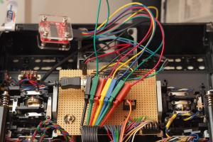
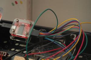
Logic Pirate attached to the mc17 LCD Logic Pirate
Open Logic Sniffer for mc17 LCD

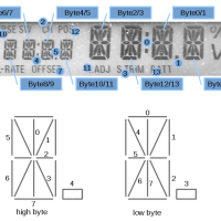
mc17 LCD mapping of bytes and bitsOnce the controller allowed me to switch on individual segments of the LCD, I needed to adapt my implementation to this specific display, as it offers remote control specific elements unusual for normal LCDs. With a proper mapping of bits and bytes to their respective LCD elements, it was easy to implement the usual alpha-numerical characters. Each of the digits is controlled by a word / two bytes. For each byte, one bit is used to control one of the additional symbols like colons, dots, or remote controls specific texts.


Cheers
Tim

Trondheim Maker Faire 2014 was great!

Thanks to all those organisers who made this awesome event possible!

After we set up our stand in the morning, we were busy until the very end. There was constant buzz of kids around, who wanted to try the ROV and steer it into one of the bucket-caves we set up in the pool. Just around closing time a managed to have a quick tour of the other stands. So nice to see all this creativity around, reminds me of the Chaos Communication Camp in 2011.
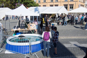
Our Stand at the Maker Faire Trondheim 2014 Our Pool
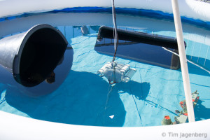
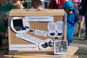
RaspiTeensyROV in the Pool RaspiTeensyROV "Schematics"

Heading out to the after-party now 🙂

PS: talking about the Chaos Communication Camp, who from Trondheim region would be interested in going there next year? I set up an etherpad here: https://pad.fnordig.de/p/trdccc15

Getting ready for the Trondheim Maker Faire

Last preparations for the upcoming Trondheim Maker Faire 2014. In order to display the Raspberry Pi / Teensy 3.1 based submersible ROV, I bought a used 3m diameter inflatable pool. This should give us enough space to demonstrate the little buddy.

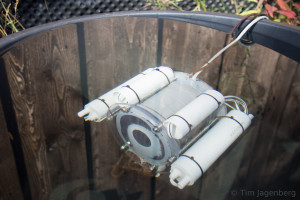
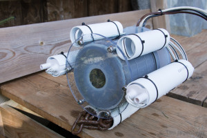
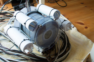
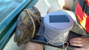
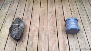
The ROV got a slight face-lift by adding proper motor-pods and casings for the cables. The ballast stones tied to the bottom got replaced by a rusty old chain in casings. Better solution pending …

RaspiTeensyROV under Water RaspiTeensyROV - front RaspiTeensyROV after Test Clas Ohlson Pool (3m)

See you at the Trondheim Maker Faire booth 10a: Map of the Faire

Submersible ROV for the Trondheim Maker Faire 2014

For the Maker Faire coming to Trondheim later this month, I’m currently building a simple submersible remotely operated vehicle. The concept is based on a plumbing tube used for the housing and submersible electric pumps as motors. A Raspberry Pi with Camera Module will deliver the live video feed via ethernet cable. The remote control is managed via a serial link to a Teensy 3.1 with sensors and motor controllers. The communication will be implemented using MAVLink, which enables the use of the QGroundControl station.

Outer Housing - Testing Outer Housing - with Ballast

After initially testing whether the tube could sustain the pressure at up to 12m water depth, pieces are now falling into place. The serial communication via MAVLink works and just needs a little performance tweaking. It can transmit the manual controls from a game-pad down to the ROV controller and the telemetry back up to the ground station. Telemetry data consists of air-pressure and temperature in the body (MPL115A2) as well as orientation data gathered from the IMU/AHRS (MPU-9150). The ground station visualises the temperature and pressure as line-graphs and uses the orientation information for an artificial horizon.

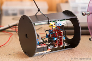
Inner Housing - View on Motor Controllers Inner Housing - View on PiCam and Raspberry Pi

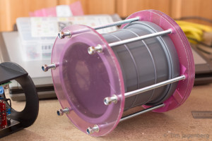
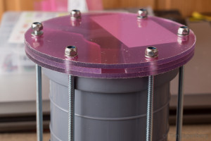
The plumbing tube of the housing is sealed with two acrylic-glass windows. One 6mm one in front of the camera and three 4mm layers in the rear end. The three layers form tunnels for the cables going out to the motors and up to the ground control station. I hope with plenty of silicone this will be water tight.

Outer Housing - Frontview Outer Casing - Channels in the Backplate

If anyone has a good idea how to set up a basin/pool to demonstrate the ROV in, let me know.
Four weeks to go! 🙂

DIY Honda CR-V Replacement Clock

As the dashboard clock of my car failed recently, I was looking for a replacement.
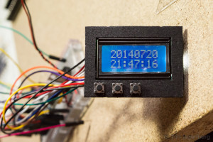
Instead of buying an original part, I opted for a DIY solution based on a cheap Arduino Pro Mini 328, a mini real-time-clock (RTC) module, and a 8×2 LCD display:

Clock Prototype on Breadboard LCD Panel with Buttons

The Arduino and the RTC module talk via I2C and the LCD uses a 4bit wide parallel interface. The LCD backlight can be switched between two intensities. It is wired to two Arduino pins at the same time, one directly and the other via a 1k resistor. The LCD draw less then 40mA. As shorting two pins can be rather dangerous for the MCU, the software needs to ensure that the inactive pin is set to high-impedance input mode before the other one is set active.

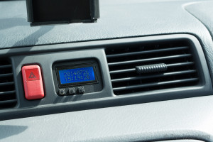
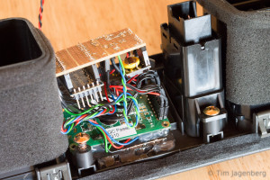
The Internals of the Dashboard Clock The new Arduino based Dashboard Clock

The initial firmware implements setting the time and manual dimming for the night. As the car-connector also offers a 12V wire indicating when the main-lights are turned on, I could add automatic dimming later on.