Teensy 3.1 I/O Extension

For the still ongoing Graupner mc-17 remote control update project, I need more I/O channels from the Teensy 3.1. By default it breaks out 28 breadboard friendly pins, but on the bottom are another 14+ solder pads with more analogue and digital I/O. By mounting the Teensy 3.1 upside-down, these solder pads become quite accessible:

Teensy 3.1 Extended (bottom is top) Teensy 3.1 Extended (top is bottom)

My ESP-03 modules arrived

Today I received the ESP-03 modules I had ordered from Shanghai. A nice little breakout for the ESP8266EX with ceramic antenna. Due to the 2mm spacing between the contacts on the sides, I had to bend the headers into shape before soldering them to the module.

ESP-03 module for the ESP8266EX

As an initial function test I used the Bus Pirate in UART bridge mode to flash the latest NodeMCU firmware onto the chip.

Hackaday Network Analysis

Being curious about the underlying structure of relations between Hackaday authors, articles, and the referenced makers, I wrote a little Java program extracting this information from publicly available data. Using jsoup and gexf4j this was a rather quick task. A simple regular expression

\[([\w\s]+)\

extracts the usual “[Tim] did this and that …” references from the Hackaday blog.

After parsing the relationships

Author [wrote] Article
Author [mentions] Maker
Article [references] Maker
Maker [mentionedWith] Maker

and saving them as an GEXF graph, the data is passed to Gephi. Gephi is a really intuitive and versatile graph visualisation tool with various options to map properties to visual appearances. It also includes a range of automated layout algorithms.

The result of playing around with the data from the last 99 blog-history pages (~from November 2014) and the many visual options of Gephi are two rather beautiful and also insightful graphs:
(green – authors, red – articles, blue – makers)

hackaday network (author-centric) hackaday network (maker-centric)

The first graph scales the nodes according to their number of outgoing relations which emphasizes the authors. The second graph scales by the incoming relations and emphasizes the makers. On the outer fringes it becomes obvious that each author has his distinct cloud of referenced blogs while the centre of the graph highlights a cluster of makers referenced by multiple authors. Another prominent feature are many smaller clusters of makers mentioned together in one or more articles. With a bit of googling, it turns out that some of these graph-relations map very nicely to personal relationships. For example two maker-nodes mentioned together very often are actually brothers in the real-world. Others turn out to be close friends.

Although all of this is public information, I left out the labels identifying authors, articles, or makers for their privacy. Especially in the context of the current debate about safety, security, and privacy, this highlights how much insight can be gained even from simple meta-data relationships.

A new Makerspace for Trondheim coming soon …

Yesterday evening I met Frode at the Digs co-working space in Trondheim. He showed me the progress of the new Makerspace in the old shelter in the basement.

Toolboard
Digs  @ Trondheim 3D Printer Screw you screws

Things are materialising and taking shape. There are workbenches around the sides, a big movable crafting table, and a wood workshop. Aside the usual soldering stations and 3d printers, there is also a rather big blackFoot router for wood and other materials.

blackFoot 4.3 router blackFoot 4.3 router - detail blackFoot 4.2 router assembly
The main area

I’m really looking forward to join and start building there. I guess the router could be interesting for wing foam cores 🙂

Low Power ESP8266 – Sleeping at 78 micro Amps

I recently bumped into NodeMCU firmware for the ESP8266. It’s an Lua interpreter, making tinkering with IoT ideas really simple. Just flash the firmware onto the ESP8266 and connect via serial console. You can start prototyping right away using the interactive Lua interpreter. You can easily persist your ideas on a simple flash file system.

print(wifi.sta.getip())
--nil
wifi.setmode(wifi.STATION)
wifi.sta.config("SSID","password")
print(wifi.sta.getip())
--192.168.13.101

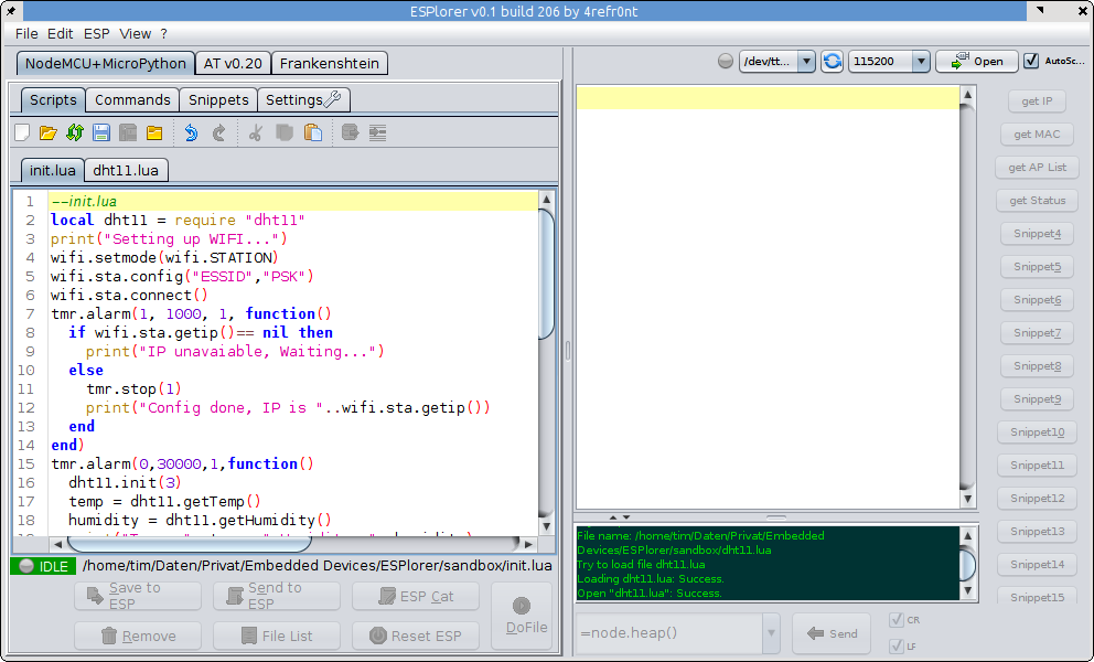
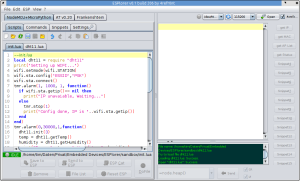
For convenient development, there is ESPlorer, a basic IDE for Lua on the NodeMCU. It allows you to develop the Lua scripts locally and then save them to the MCU via serial protocol.
ESPlorer

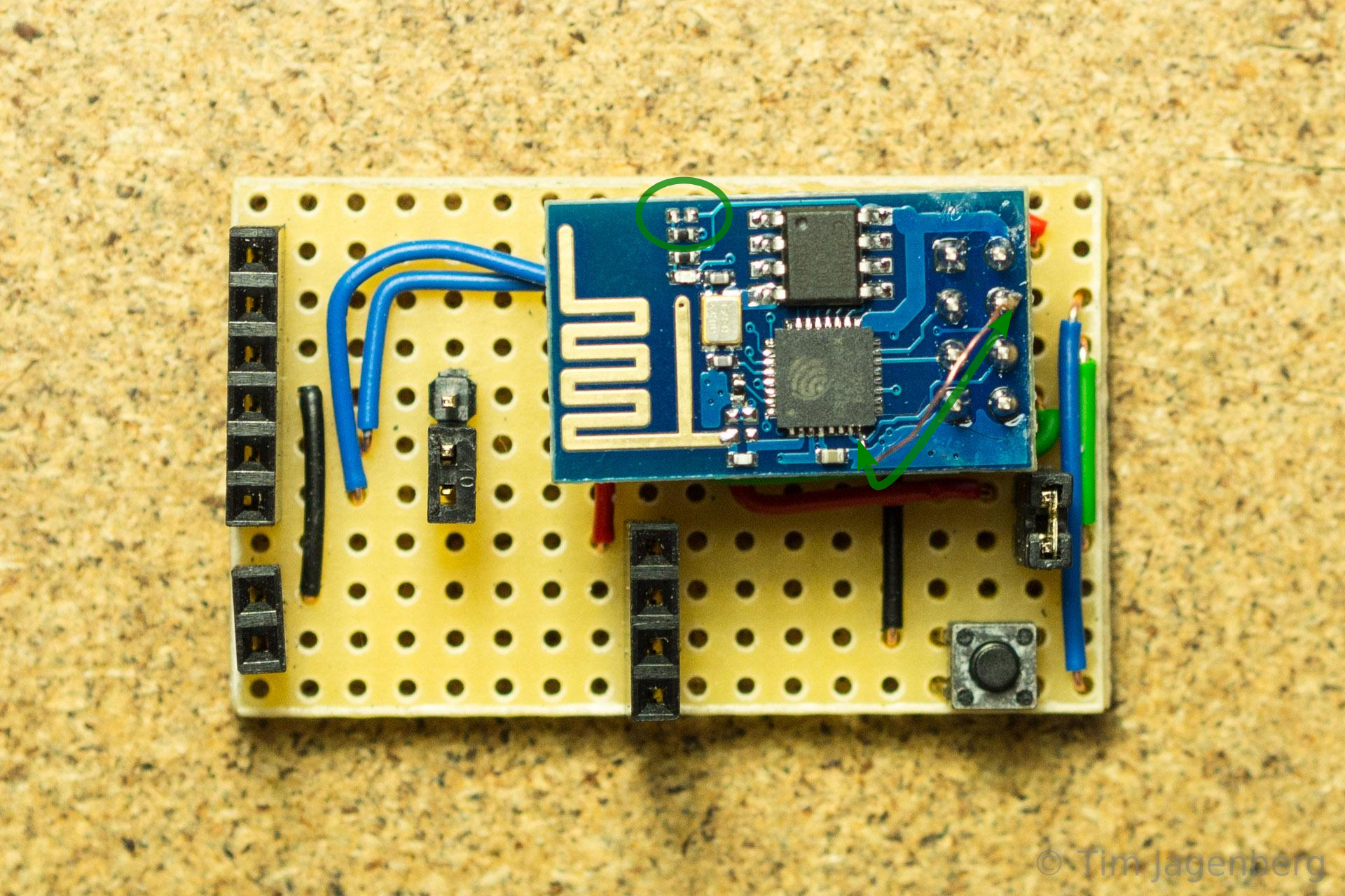
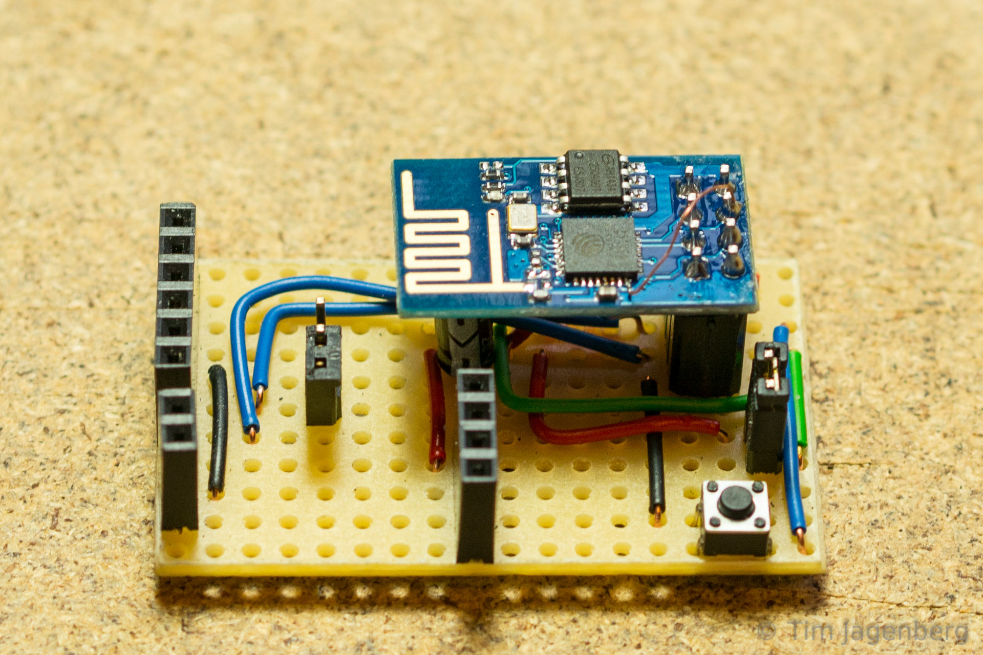
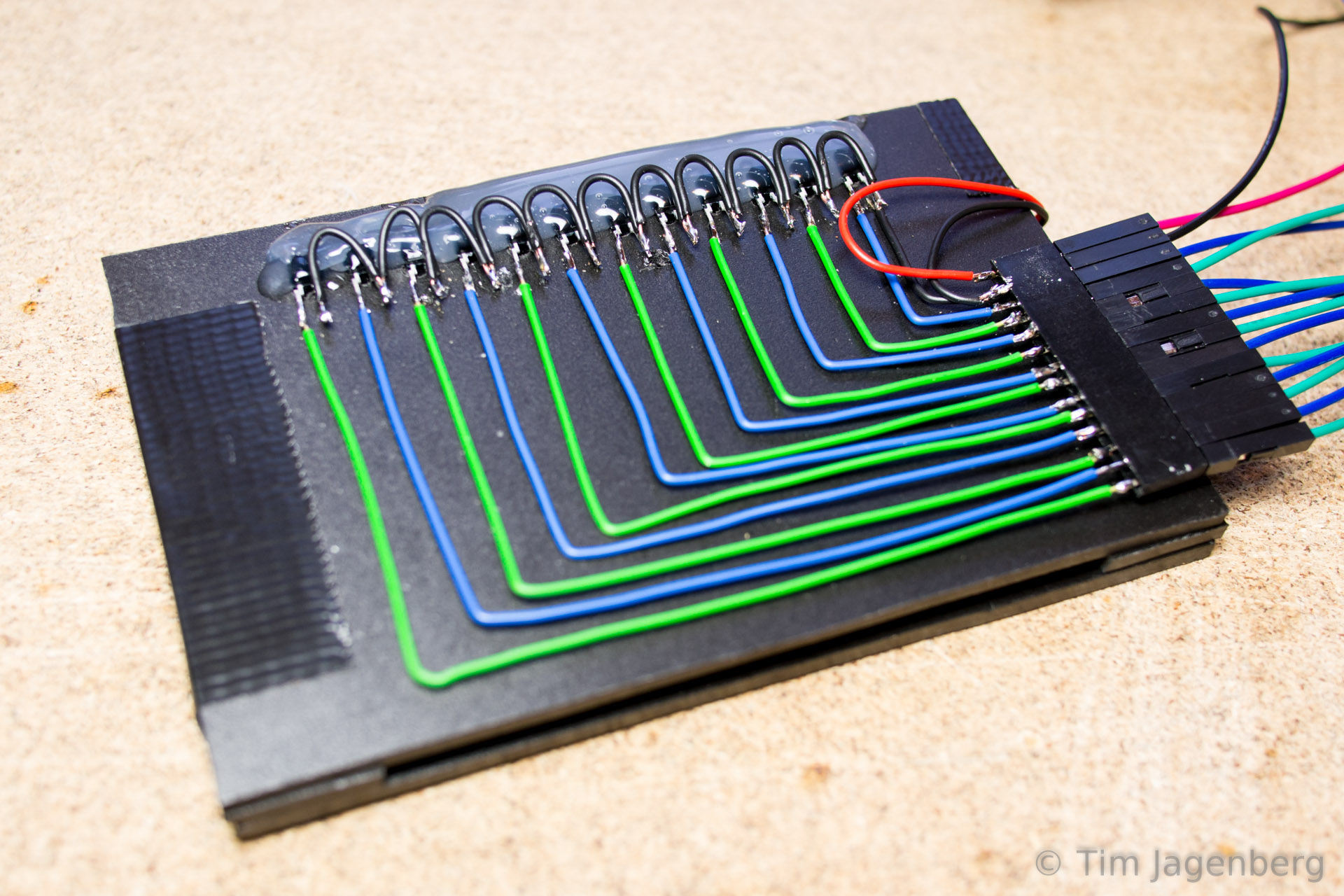
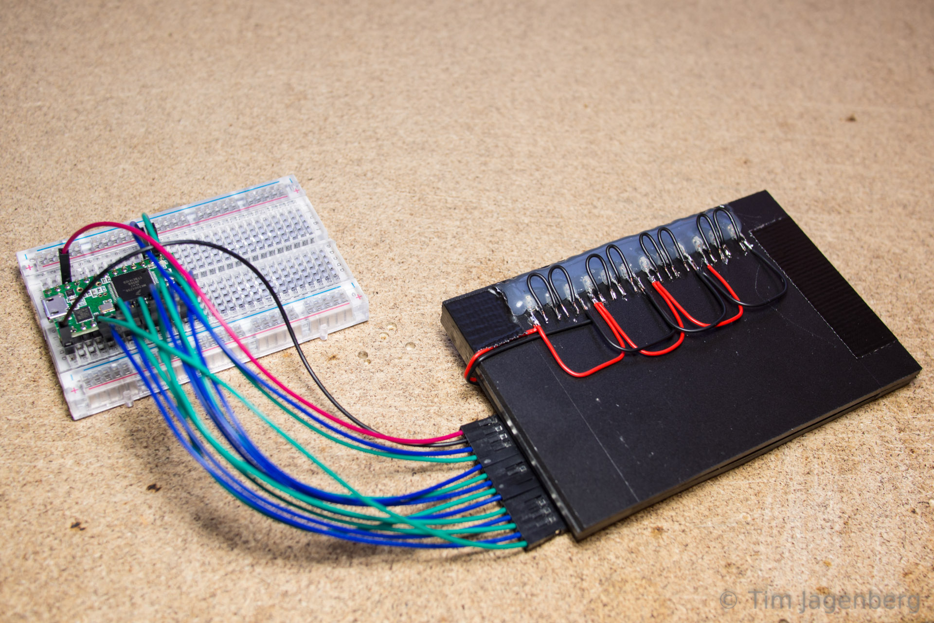
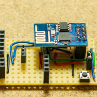
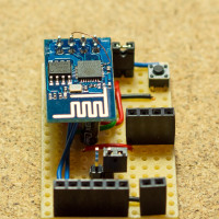
To make developing with the ESP-01 module easier, I created a basic development board. It provides easier access to the individual pins, has jumpers for flashing mode (GPIO00) and enable (CH_PD), offers a button for reset, and also integrates a socket for a step-down power supply.
ESP8266 (ESP-01) dev board top-view ESP8266 (ESP-01) dev board side-view
ESP8266 (ESP-01) dev board front-view ESP8266 Development Board

Although NodeMCU provides access to the deep-sleep mode of the ESP8266

node.dsleep(microSecs);

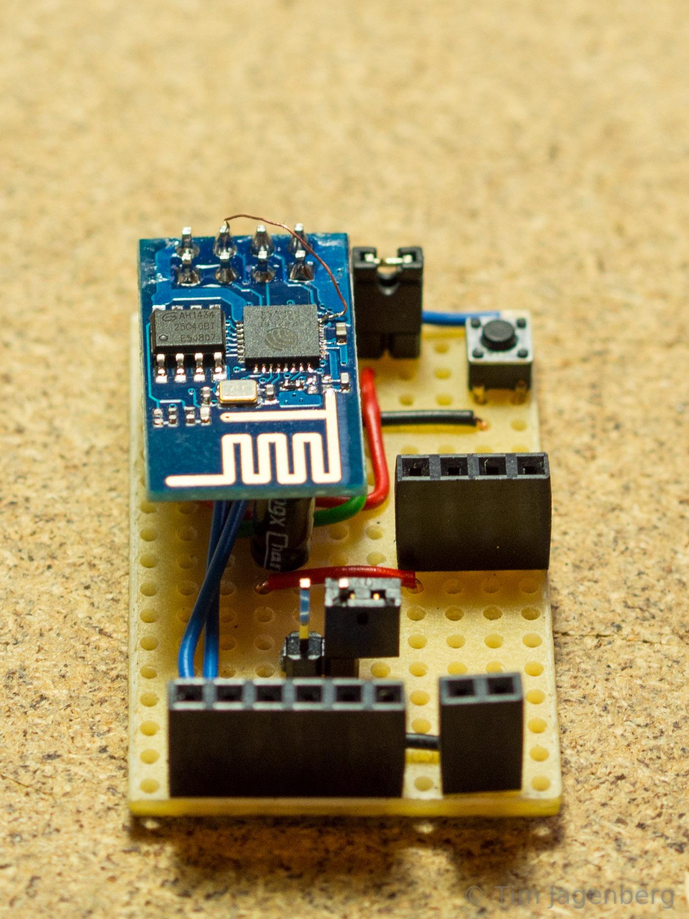
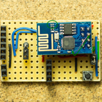
this is not available straight away on the ESP-01 module, as the ‘post-sleep-reset-pin’ XPD_DCDC (8) of the MCU is not connected to the reset pin. I solved this by manually soldering a single wire of a stranded cable between the reset pin of the module and the XPD_DCDC (8) pin of the MCU (bottom right corner of the mcu in the first photo). On top of this, I also removed the red power LED by simply prying it off with a tiny screw driver.
With these two modifications, the module is able to make use of the deep-sleep mode and successfully resets and restarts after waking.

During deep sleep the module now uses just 78 microAmps! On two normal AA batteries with 2600mAh, that’s good for well over 3 years!

Update 2015-04-12:

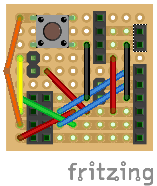
Due to frequent questions about the Fritzing file or schematics, I uploaded the Fritzing file:
ESP-01_ESP8266_Board.fzz
(if the file extension gets mixed up, apply .fzz manually)

Update 2015-11-18:

Marv Marvelous over at http://blog.grafovision.sk/ translated this article into Slovak. Thanks Marv!

Punching a Card

Both hackaday and make blogged about the punch card reader I put together recently. As manually punching a card is quite a quite an effort, punchcard_gw@twitter has been rather quiet since the initial ‘HELLO WORLD!’

In reply to their posts, I punched another card ‘THANKS FOR THE POSTS @HACKADAY @MAKE’ and documented the process in more detail:

Ready to punch a card Preparing the card Punching the card

Punch Card to Twitter

"HELLO WORLD!"

The above line was actually directly written from an old-fashioned punch card! How? Via my DIY punch-card-to-keyboard interface 😉

It all started with a conversation with a colleague about the good-old-times of computers, when de-bugging was still removing live animals. A few days later he dropped by my office and handed me a bunch of cards of ‘Druckwerke Reichenbach’.

punched card - HELLO WORLD! first prototype - mechanical punch card reader

Initially I tried reading the cards with a mechanical contact, but this quickly turned out to be highly unreliable. Around the same time I had disassembled some old HP office print stations, which resulted in a large number of useful parts. Some stepper motors, some solenoids, and heaps of slotted optical interrupter switches. Following a tip of another colleague, I started disassembling the switches into IR-LEDs and corresponding photo-transistors.

disassembling optical switches optical punched card reader prototype - the left-overs

Using these components I build a new prototype, this time using contactless optical sensors. I drilled opposing holes into two plastic cards. On one side I glued the LEDs and on the other side the photo-transistors. The LEDs are powered by 3.3V chaining 3 LEDs serial and 4 groups parallel. The transistors use a common ground and are connected to the Teensy 3.1 inputs. The inputs have activated pull-up resistors, pulling them to 3.3V as well. With a free passage between the LED and the transistor, the light activates the transistor, which in turn pulls the input to ground. With the card in between, the transistor receives no light and let’s the input be pulled up to 3.3V. Thus the input pins follow an inverted logic.

optical punched card reader prototype - holes for the leds optical punched card reader prototype - installing the leds

The two plastic plates are separated by two plastic guides to each side of the card. They provide guidance to the card when inserted, which is important for the correct hole alignment. As the optical card reader turned out to work rather reliable, I implemented a simple interpreter on the Teensy 3.1 which reads the card according to the IBM model 029 keypunch from the 60’s / 70’s. The micro-controller is recognised as a USB HID keyboard and sends the decoded characters as key presses. Each card is finalised with an ‘enter’ key press. The only adjustments I made are to only use every second column of the card in order to make sure all contacts close after each character. Also I added a space character encoding (Y&X row). You can download the binary and source code for the Teensy 3.1 based decoder from github.

optical punched card reader prototype - the switch side optical punched card reader prototype - wired to the Teensy 3.1

Now all that’s left is to do is to use this device and send a ‘HELLO WORLD!’ tweet directly from punch card 🙂