Drone King of the Hill

The recent Hak5 episode 1903 inspired me to build a King of the Hill version for quadcopters. Shannon and Darren talked about their acrylic drone-fighting cage, the last-man-standing matches they had, and their future plans including a version of king of the hill.

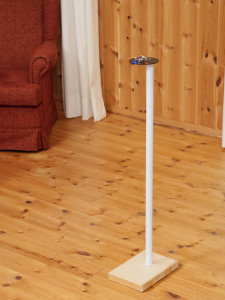
Since then, I’ve been working on my own implementation of the king of the hill idea based on an old ADJD-S311 Color Light Sensor Evaluation Board from Sparkfun which I still had lying around. Combined with an Pololu A-Star 32U4 Micro for the brains, a single button for input, and an LPD8806 based RGB-LED-strip from Adafruit for output, this made a pretty nice tinkering project.

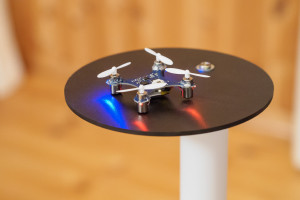
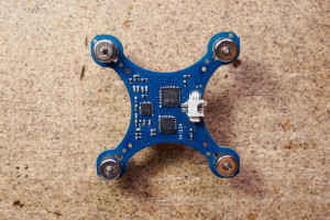
Micro Quadcopter Micro Quadrcopter on Platform

The micro quadcopters are split into 2 to 4 teams and are marked with differently coloured stickers at the bottom (red, green, blue, yellow).
The light sensor in the centre of the platform is initially passive and set to maximum sensitivity. In combination with ambient light, the A-Star Micro can detect whether the sensor is covered or not. As soon as it detects that the sensor is covered, it is set to active mode. It then evaluates reflected light using a white LED and a lower sensitivity setting. Based on the measured rgb-colour, ‘the brains’ decide which team the drone on the platform belongs to.
After a team covered the sensor for 3 seconds to win a point, the platform needs to be cleared for 5 seconds before another winning point can be gained.

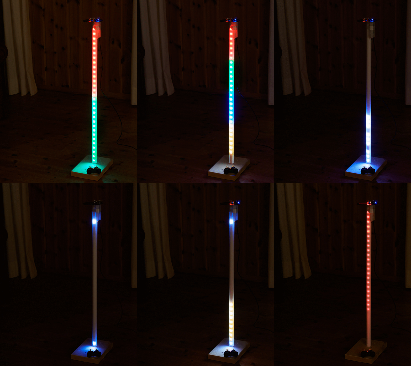
Drone King of the Hill Gameย ย  Drone King of the Hill Game (animated)

The game play is set-up using the single button. First the number of teams is shown using the LEDs in the vertical stand. Clicking the button iterates between 2, 3, or 4 teams with different colours. After a long-click, the number of winning points are selected. Again by clicking the button 1, 3, 5, or 7 winning points can be selected. The game starts after another long-click with the progress being displayed on the vertical bar. As only a single LED strip is used, additive colour mixing occurs between the teams. The game continues until one of the teams achieves the necessary number of points, upon which the winning team’s colour flashes along the bar in ‘knight rider’ fashion.

Some friends from FIX, the local maker space, and I ordered a whole bunch of Eachine H8 Mini drones. Now we’re looking forward to some awesome team matches the space ๐Ÿ™‚

The CAD models can be found at Onshape, a really interesting web-based CAD solution done by veterans of Solidworks. (log-in and search for ‘Drone King of the Hill’, couldn’t find a public link … still beta ๐Ÿ˜‰ )
The source code can be found on GitHub and relies on the awesome cross-platform code builder and library manager PlatformIO.

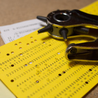
Punching a Card

Both hackaday and make blogged about the punch card reader I put together recently. As manually punching a card is quite a quite an effort, punchcard_gw@twitter has been rather quiet since the initial ‘HELLO WORLD!’

In reply to their posts, I punched another card ‘THANKS FOR THE POSTS @HACKADAY @MAKE’ and documented the process in more detail:

Ready to punch a card Preparing the card Punching the card

Punch Card to Twitter

"HELLO WORLD!"

The above line was actually directly written from an old-fashioned punch card! How? Via my DIY punch-card-to-keyboard interface ๐Ÿ˜‰

It all started with a conversation with a colleague about the good-old-times of computers, when de-bugging was still removing live animals. A few days later he dropped by my office and handed me a bunch of cards of ‘Druckwerke Reichenbach’.

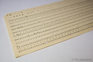
punched card - HELLO WORLD! first prototype - mechanical punch card reader

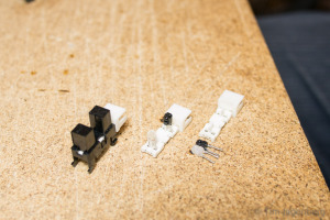
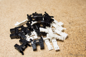
Initially I tried reading the cards with a mechanical contact, but this quickly turned out to be highly unreliable. Around the same time I had disassembled some old HP office print stations, which resulted in a large number of useful parts. Some stepper motors, some solenoids, and heaps of slotted optical interrupter switches. Following a tip of another colleague, I started disassembling the switches into IR-LEDs and corresponding photo-transistors.

disassembling optical switches optical punched card reader prototype - the left-overs

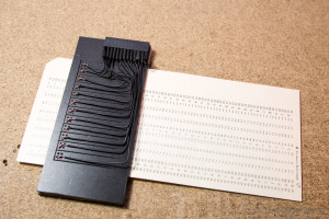
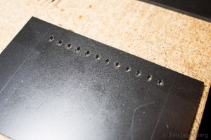
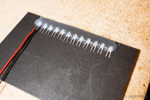
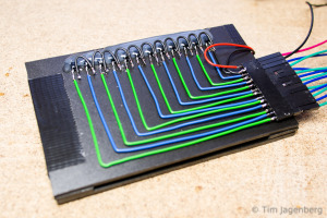
Using these components I build a new prototype, this time using contactless optical sensors. I drilled opposing holes into two plastic cards. On one side I glued the LEDs and on the other side the photo-transistors. The LEDs are powered by 3.3V chaining 3 LEDs serial and 4 groups parallel. The transistors use a common ground and are connected to the Teensy 3.1 inputs. The inputs have activated pull-up resistors, pulling them to 3.3V as well. With a free passage between the LED and the transistor, the light activates the transistor, which in turn pulls the input to ground. With the card in between, the transistor receives no light and let’s the input be pulled up to 3.3V. Thus the input pins follow an inverted logic.

optical punched card reader prototype - holes for the leds optical punched card reader prototype - installing the leds

The two plastic plates are separated by two plastic guides to each side of the card. They provide guidance to the card when inserted, which is important for the correct hole alignment. As the optical card reader turned out to work rather reliable, I implemented a simple interpreter on the Teensy 3.1 which reads the card according to the IBM model 029 keypunch from the 60’s / 70’s. The micro-controller is recognised as a USB HID keyboard and sends the decoded characters as key presses. Each card is finalised with an ‘enter’ key press. The only adjustments I made are to only use every second column of the card in order to make sure all contacts close after each character. Also I added a space character encoding (Y&X row). You can download the binary and source code for the Teensy 3.1 based decoder from github.

optical punched card reader prototype - the switch side optical punched card reader prototype - wired to the Teensy 3.1

Now all that’s left is to do is to use this device and send a ‘HELLO WORLD!’ tweet directly from punch card ๐Ÿ™‚

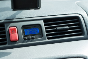
DIY Honda CR-V Replacement Clock

As the dashboard clock of my car failed recently, I was looking for a replacement.
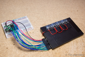
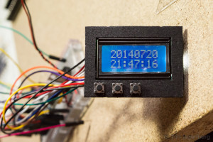
Instead of buying an original part, I opted for a DIY solution based on a cheap Arduino Pro Mini 328, a mini real-time-clock (RTC) module, and a 8×2 LCD display:

Clock Prototype on Breadboard LCD Panel with Buttons

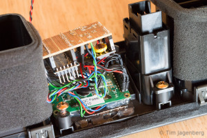
The Arduino and the RTC module talk via I2C and the LCD uses a 4bit wide parallel interface. The LCD backlight can be switched between two intensities. It is wired to two Arduino pins at the same time, one directly and the other via a 1k resistor. The LCD draw less then 40mA. As shorting two pins can be rather dangerous for the MCU, the software needs to ensure that the inactive pin is set to high-impedance input mode before the other one is set active.

The Internals of the Dashboard Clock The new Arduino based Dashboard Clock

The initial firmware implements setting the time and manual dimming for the night. As the car-connector also offers a 12V wire indicating when the main-lights are turned on, I could add automatic dimming later on.

New Tinker Toys

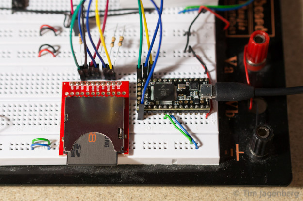
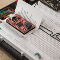
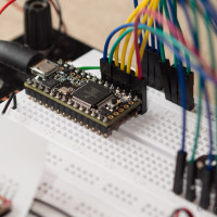
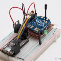
In the recent weeks I found more time for tinkering and received a whole range of new toys: Two bread-board friendly micro-controller boards (Embedded Artists’ LPC1343 QuickStart Board and PJRC Teensy 3.1), the Pi NoIR Camera, two XBee Pro S2B serial RF modules, and plenty of other i2c sensors and generic tinkering supplies. On the EA QuickStart Board, which uses the same MCU as the r0ket, I’m running the microBuilder LPC1343 Code Base and the Teensy 3.1 is Arduino compatible which enables me to make use of a huge range of ready-made libraries for pretty much all my breakout boards.
Embedded Artists LPC1343 QuickStart Board PJRC Teensy 3.1 XBee Pro S2B

One of my current projects is to exchange the micro-controller of my old Graupner mc-17 remote control with the Teensy 3.1. I removed the old processor board and added contacts to all the existing connections: 2X6 poles for analogue measurements of the sticks and trims, and 2X8 poles for the LCD controller and the buttons. The LCD controller is a NEC mPD7225 for which I already found a data sheet. Via the 12bit analogue output of the Teensy, I can even drive the old analogue ammeter at the front of the remote! ๐Ÿ™‚
Graupner mc-17 top Graupner mc-17 original controller removed Graupner mc-17 teensy 3.1 controller

Let’s see how well this mc-17 > Teensy 3.1 > XBee ~ XBee > Teensy 3.1 remote control chain works ๐Ÿ˜‰

Cheers
Tim