Teensy 3.1 I/O Extension

For the still ongoing Graupner mc-17 remote control update project, I need more I/O channels from the Teensy 3.1. By default it breaks out 28 breadboard friendly pins, but on the bottom are another 14+ solder pads with more analogue and digital I/O. By mounting the Teensy 3.1 upside-down, these solder pads become quite accessible:

Teensy 3.1 Extended (bottom is top) Teensy 3.1 Extended (top is bottom)

Punching a Card

Both hackaday and make blogged about the punch card reader I put together recently. As manually punching a card is quite a quite an effort, punchcard_gw@twitter has been rather quiet since the initial ‘HELLO WORLD!’

In reply to their posts, I punched another card ‘THANKS FOR THE POSTS @HACKADAY @MAKE’ and documented the process in more detail:

Ready to punch a card Preparing the card Punching the card

Punch Card to Twitter

"HELLO WORLD!"

The above line was actually directly written from an old-fashioned punch card! How? Via my DIY punch-card-to-keyboard interface 😉

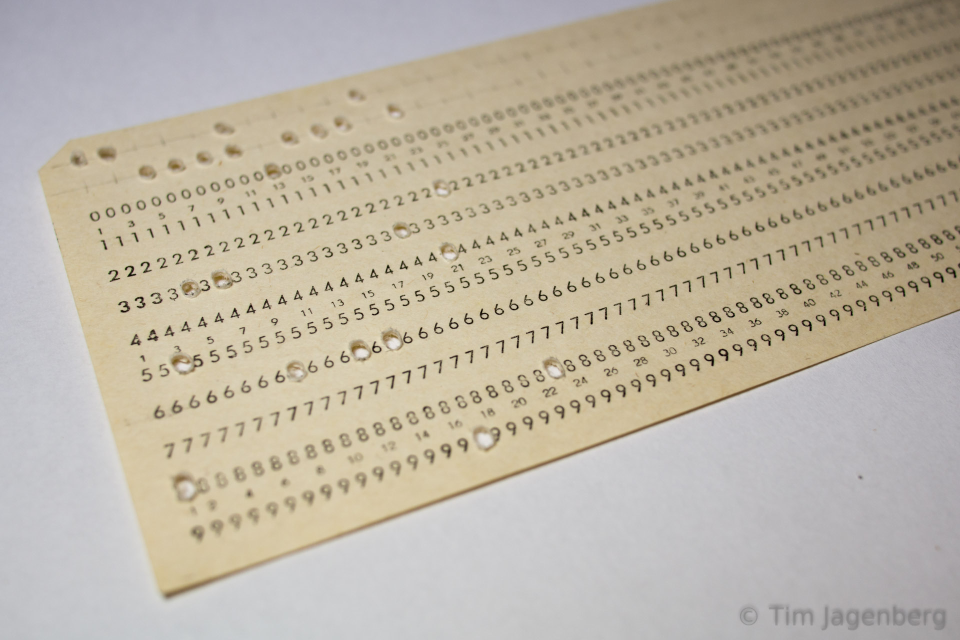
It all started with a conversation with a colleague about the good-old-times of computers, when de-bugging was still removing live animals. A few days later he dropped by my office and handed me a bunch of cards of ‘Druckwerke Reichenbach’.

punched card - HELLO WORLD! first prototype - mechanical punch card reader

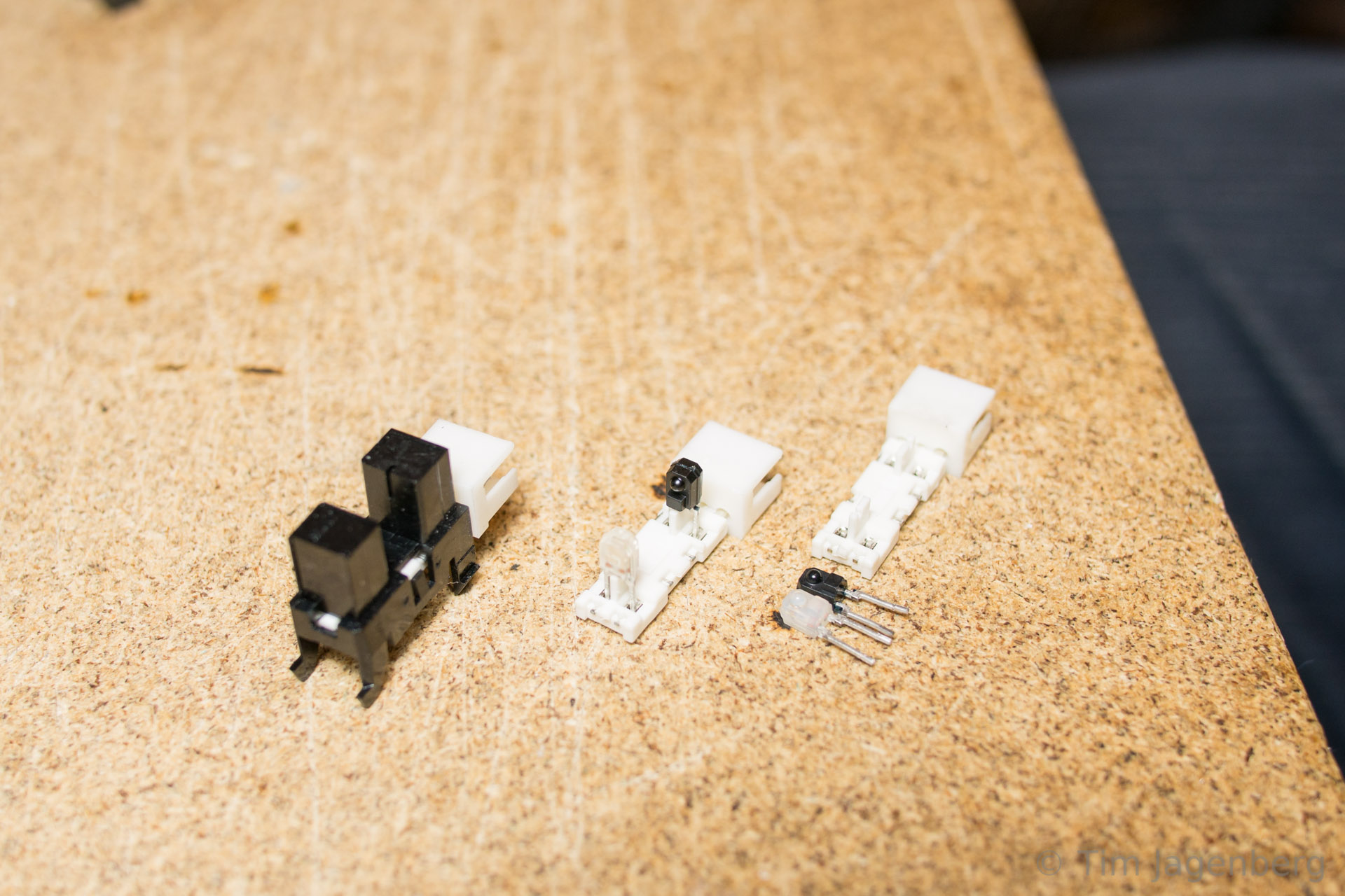
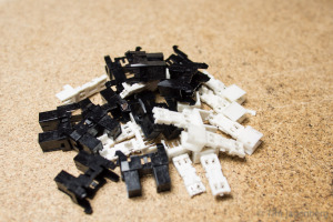
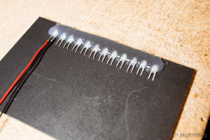
Initially I tried reading the cards with a mechanical contact, but this quickly turned out to be highly unreliable. Around the same time I had disassembled some old HP office print stations, which resulted in a large number of useful parts. Some stepper motors, some solenoids, and heaps of slotted optical interrupter switches. Following a tip of another colleague, I started disassembling the switches into IR-LEDs and corresponding photo-transistors.

disassembling optical switches optical punched card reader prototype - the left-overs

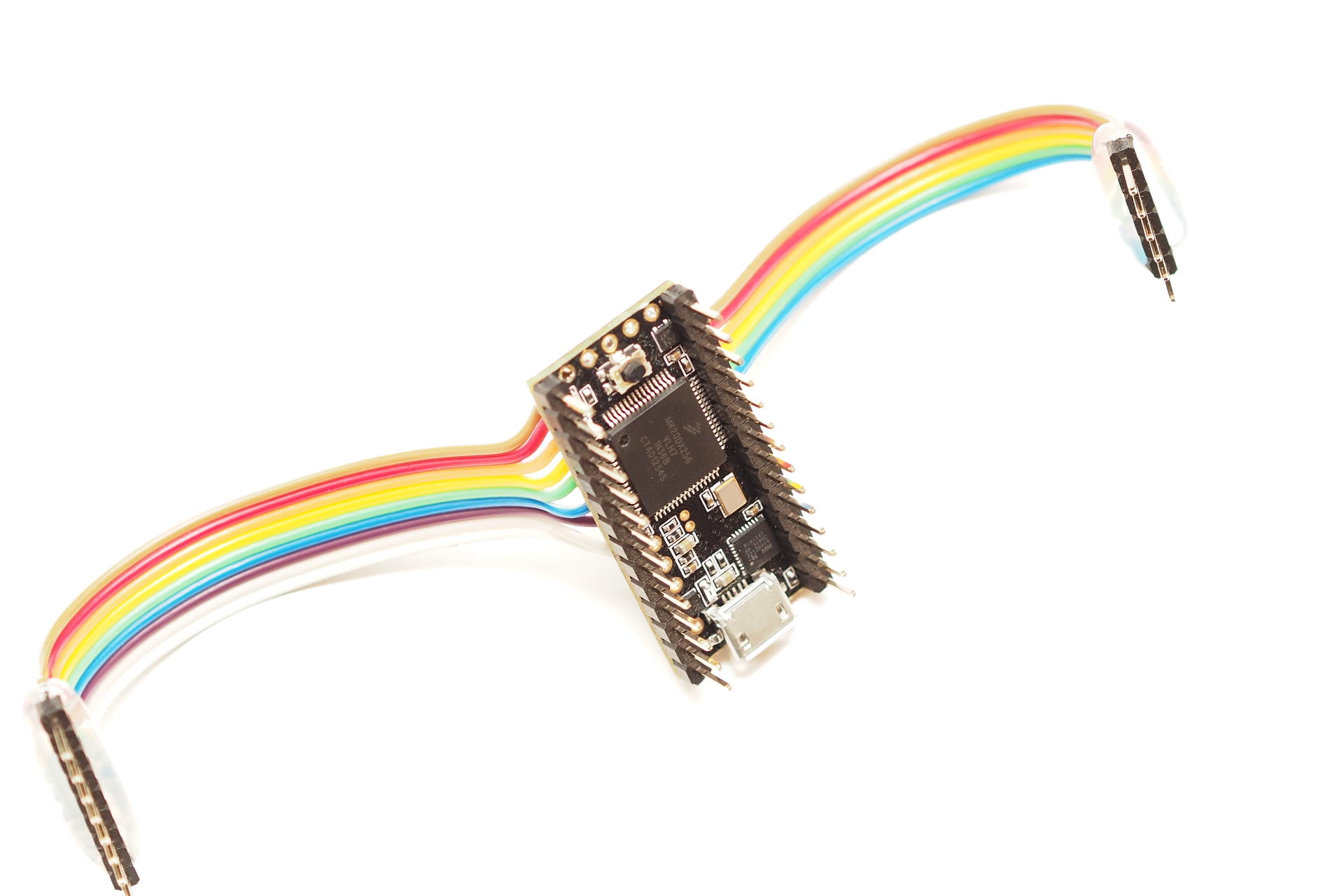
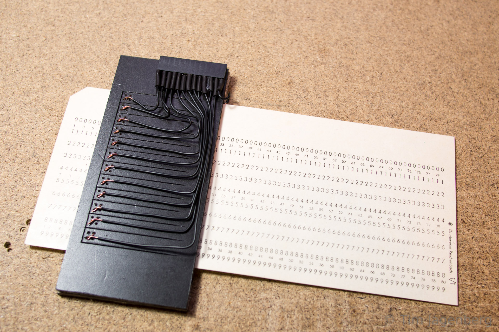
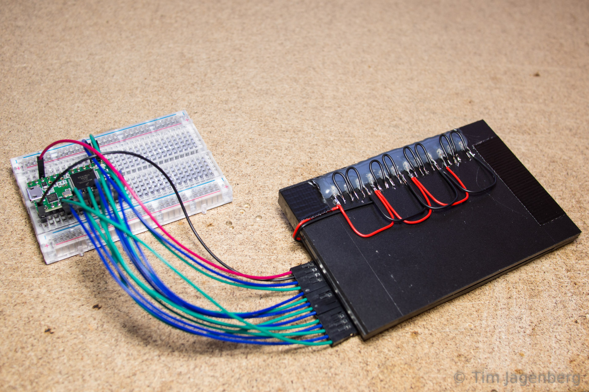
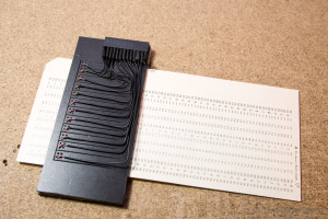
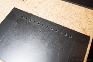
Using these components I build a new prototype, this time using contactless optical sensors. I drilled opposing holes into two plastic cards. On one side I glued the LEDs and on the other side the photo-transistors. The LEDs are powered by 3.3V chaining 3 LEDs serial and 4 groups parallel. The transistors use a common ground and are connected to the Teensy 3.1 inputs. The inputs have activated pull-up resistors, pulling them to 3.3V as well. With a free passage between the LED and the transistor, the light activates the transistor, which in turn pulls the input to ground. With the card in between, the transistor receives no light and let’s the input be pulled up to 3.3V. Thus the input pins follow an inverted logic.

optical punched card reader prototype - holes for the leds optical punched card reader prototype - installing the leds

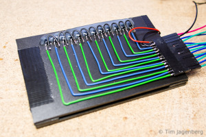
The two plastic plates are separated by two plastic guides to each side of the card. They provide guidance to the card when inserted, which is important for the correct hole alignment. As the optical card reader turned out to work rather reliable, I implemented a simple interpreter on the Teensy 3.1 which reads the card according to the IBM model 029 keypunch from the 60’s / 70’s. The micro-controller is recognised as a USB HID keyboard and sends the decoded characters as key presses. Each card is finalised with an ‘enter’ key press. The only adjustments I made are to only use every second column of the card in order to make sure all contacts close after each character. Also I added a space character encoding (Y&X row). You can download the binary and source code for the Teensy 3.1 based decoder from github.

optical punched card reader prototype - the switch side optical punched card reader prototype - wired to the Teensy 3.1

Now all that’s left is to do is to use this device and send a ‘HELLO WORLD!’ tweet directly from punch card 🙂

Back to the mc-17 Remote Control

After the Maker Faire, I went back to the Graupner mc-17 remote control.

The arduino library from tronixstuff for the KTM-S1201 LCD which is also using a mPD7225 controller was a good starting point. But to get the LCD up and running, it took quite a bit of fiddling and logic sniffing.

Logic Pirate attached to the mc17 LCD Logic Pirate
Open Logic Sniffer for mc17 LCD

mc17 LCD mapping of bytes and bitsOnce the controller allowed me to switch on individual segments of the LCD, I needed to adapt my implementation to this specific display, as it offers remote control specific elements unusual for normal LCDs. With a proper mapping of bits and bytes to their respective LCD elements, it was easy to implement the usual alpha-numerical characters. Each of the digits is controlled by a word / two bytes. For each byte, one bit is used to control one of the additional symbols like colons, dots, or remote controls specific texts.


Cheers
Tim

Trondheim Maker Faire 2014 was great!

Thanks to all those organisers who made this awesome event possible!

After we set up our stand in the morning, we were busy until the very end. There was constant buzz of kids around, who wanted to try the ROV and steer it into one of the bucket-caves we set up in the pool. Just around closing time a managed to have a quick tour of the other stands. So nice to see all this creativity around, reminds me of the Chaos Communication Camp in 2011.
Our Stand at the Maker Faire Trondheim 2014 Our Pool
RaspiTeensyROV in the Pool RaspiTeensyROV "Schematics"

Heading out to the after-party now 🙂

PS: talking about the Chaos Communication Camp, who from Trondheim region would be interested in going there next year? I set up an etherpad here: https://pad.fnordig.de/p/trdccc15

Getting ready for the Trondheim Maker Faire

Last preparations for the upcoming Trondheim Maker Faire 2014. In order to display the Raspberry Pi / Teensy 3.1 based submersible ROV, I bought a used 3m diameter inflatable pool. This should give us enough space to demonstrate the little buddy.

The ROV got a slight face-lift by adding proper motor-pods and casings for the cables. The ballast stones tied to the bottom got replaced by a rusty old chain in casings. Better solution pending …

RaspiTeensyROV under Water RaspiTeensyROV - front RaspiTeensyROV after Test Clas Ohlson Pool (3m)

See you at the Trondheim Maker Faire booth 10a: Map of the Faire

Submersible ROV for the Trondheim Maker Faire 2014

For the Maker Faire coming to Trondheim later this month, I’m currently building a simple submersible remotely operated vehicle. The concept is based on a plumbing tube used for the housing and submersible electric pumps as motors. A Raspberry Pi with Camera Module will deliver the live video feed via ethernet cable. The remote control is managed via a serial link to a Teensy 3.1 with sensors and motor controllers. The communication will be implemented using MAVLink, which enables the use of the QGroundControl station.

Outer Housing - Testing Outer Housing - with Ballast

After initially testing whether the tube could sustain the pressure at up to 12m water depth, pieces are now falling into place. The serial communication via MAVLink works and just needs a little performance tweaking. It can transmit the manual controls from a game-pad down to the ROV controller and the telemetry back up to the ground station. Telemetry data consists of air-pressure and temperature in the body (MPL115A2) as well as orientation data gathered from the IMU/AHRS (MPU-9150). The ground station visualises the temperature and pressure as line-graphs and uses the orientation information for an artificial horizon.

Inner Housing - View on Motor Controllers Inner Housing - View on PiCam and Raspberry Pi

The plumbing tube of the housing is sealed with two acrylic-glass windows. One 6mm one in front of the camera and three 4mm layers in the rear end. The three layers form tunnels for the cables going out to the motors and up to the ground control station. I hope with plenty of silicone this will be water tight.

Outer Housing - Frontview Outer Casing - Channels in the Backplate

If anyone has a good idea how to set up a basin/pool to demonstrate the ROV in, let me know.
Four weeks to go! 🙂