Just a colourful photo of my newest acquisition, the Bus Pirate v3.6 in a quick 2hr diy plexiglass case:
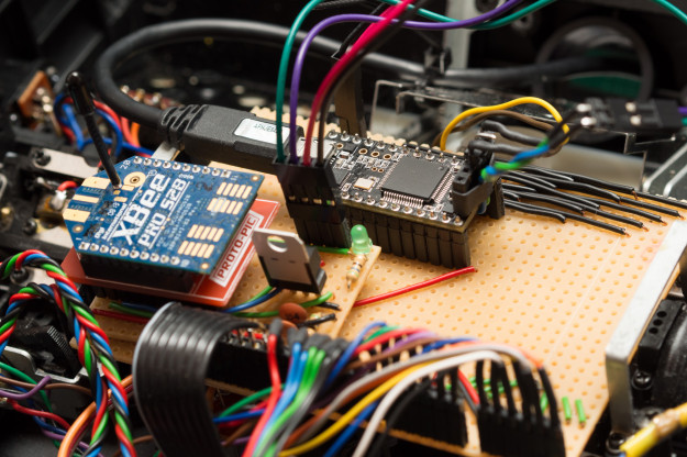
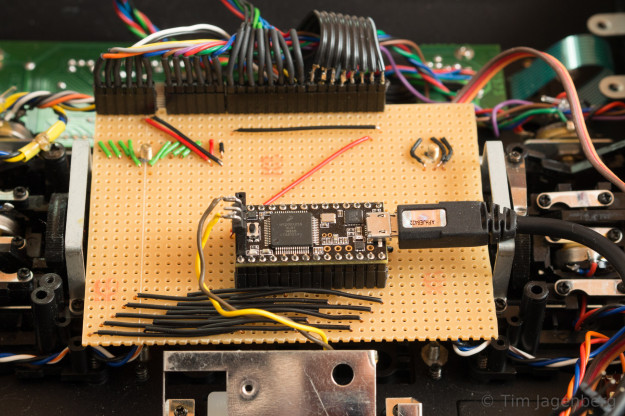
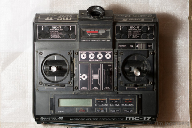
mc-17 working with teensy-3.1 & XBee
With all the connections for the analogue sticks, the analogue output, the lcd-control, and the buttons, the 28 standard pins of the Teensy 3.1 were used up. In order to connect the XBee Pro S2B with the Teensy, I had to use the solder-pads on the bottom of the pcb. After all the work was done, I realised that using those pads for Serial2 instead of the standard pins was more difficult than anticipated. Thanks to the tips from the PJRC Teensy community forum, I managed to get the serial link working.
With all the peripherals set up, I still have to figure out how to drive the lcd, as the panel used in the mc-17 differs from the standard alpha-numeric ones.
Updating an old Remote Control
I recently replaced the controller of my old Graupner mc-17 remote control with a current ARM Cortex-M4 @ 96MHz (Teensy 3.1). Yesterday I soldered the sockets for the LCD, the buttons, and the ammeter which gives me access to almost all peripherals (only the power switch and the additional linear channel are still missing). I already found an Arduino library for the LCD controller NEC mPD7225, thanks tronixstuff, but the display which Graupner used differs from the standard one. Basically the LCD works, but the demo sketch just gives scrambled output. I guess I’ll have to reverse-engineer this application specific LCD.
Teensy 3.1 & SD-Cards
Reading & writing data from/to a SD Card using a Teensy 3.1 and SD/MM card breakout board:
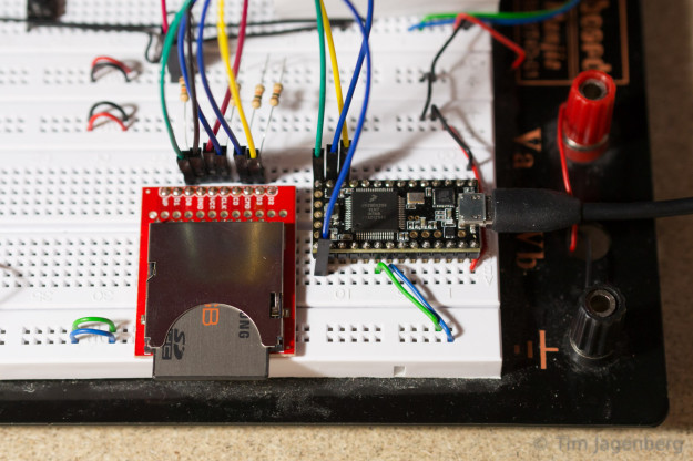
Don’t forget the 10kOhm pull-up resistors on the digital pins (not GND and VCC). 😉
Just a little tinkering around …
New Tinker Toys
In the recent weeks I found more time for tinkering and received a whole range of new toys: Two bread-board friendly micro-controller boards (Embedded Artists’ LPC1343 QuickStart Board and PJRC Teensy 3.1), the Pi NoIR Camera, two XBee Pro S2B serial RF modules, and plenty of other i2c sensors and generic tinkering supplies. On the EA QuickStart Board, which uses the same MCU as the r0ket, I’m running the microBuilder LPC1343 Code Base and the Teensy 3.1 is Arduino compatible which enables me to make use of a huge range of ready-made libraries for pretty much all my breakout boards.
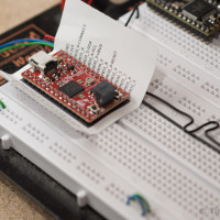
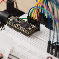
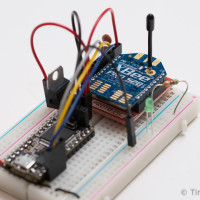
One of my current projects is to exchange the micro-controller of my old Graupner mc-17 remote control with the Teensy 3.1. I removed the old processor board and added contacts to all the existing connections: 2X6 poles for analogue measurements of the sticks and trims, and 2X8 poles for the LCD controller and the buttons. The LCD controller is a NEC mPD7225 for which I already found a data sheet. Via the 12bit analogue output of the Teensy, I can even drive the old analogue ammeter at the front of the remote! 🙂


Let’s see how well this mc-17 > Teensy 3.1 > XBee ~ XBee > Teensy 3.1 remote control chain works 😉
Cheers
Tim
RPi2C
I recently ordered a bunch of I2C breakout boards to tinker around with. The first thing I implemented, using the Pi4J library, was a simple eight by eight version of Conway’s Game of Life using an I2C controlled bicolor LED matrix from Adafruit.
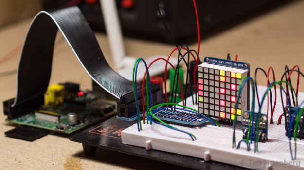
Next I build a simple two-wheeled robotic platform (RPi2C) to test the 9DOF MPU9150 breakout board from Sparfun. This little chip integrates accelerometer, gyroscope, and magnetometer into a single package and also includes what Invensense calls a digital motion processor for on-board sensor fusion.
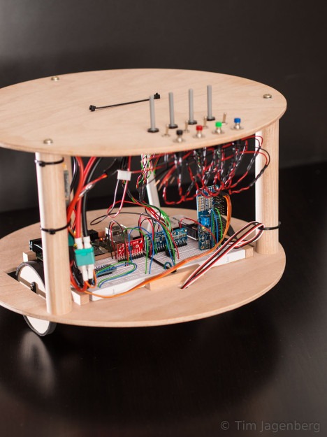
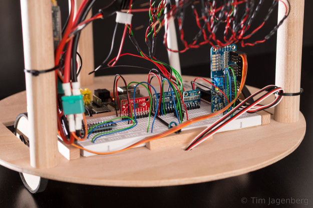
The two wheels are driven by basic Parallax continuous rotation servos and controlled by the same I2C based PCA9685 breakout board from Adafruit I already used on the RaspberryPylot. As the MPU9150 DMP requires uploading of firmware via I2C which I still need to implement, I’m currently simply using the raw gyro data and a PID controller for very basic stabilisation. Also the low rotational speed of the servo motors limits the ability to recover from disturbances. Fusing the sensor data of the accelerometer and the gyro, an improved controller, and maybe stronger motors should deliver better results, soon.
The platform also includes a basic bread-board, a bunch of potentiometers, switches, and buttons, as well as an ADS1115 16-Bit ADC and a SX1509 16 Output I/O Expander for happy tinkering. 😉
Maiden-Flight RaspberryPylot
RaspberryPylot made it!
With perfect weather and a great ground-team supplying me with food, the RaspberryPylot successfully completed its maiden-flight today. A laptop with gamepad, a wifi-connection using two simple USB dongles, an I2C servo controller and a Raspberry Pi and it’s ready to go:
Control via the gamepad was very comfortable and easy. Two analogue sticks for elevator, rudder, and ailerons. Two buttons to increase and decrease throttle and another two buttons to control the ailerons as flaps (flaperons). We didn’t test the master/slave mode today, but one can attach two gamepads and use one master button to switch between both with independent control profiles for each mode. In principle one could pass over the control of only one single axis at a time.
Many thanks to the CRRCSim team for creating such a fun way of training pre-flight.
Cheers
Tim


