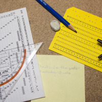
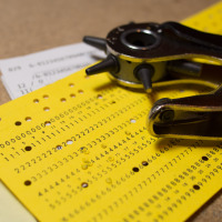
"HELLO WORLD!"
The above line was actually directly written from an old-fashioned punch card! How? Via my DIY punch-card-to-keyboard interface 😉
It all started with a conversation with a colleague about the good-old-times of computers, when de-bugging was still removing live animals. A few days later he dropped by my office and handed me a bunch of cards of ‘Druckwerke Reichenbach’.
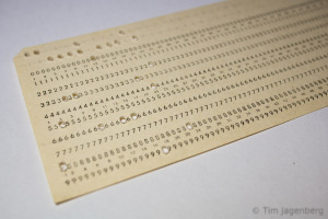
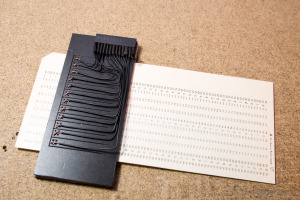
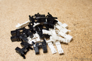
Initially I tried reading the cards with a mechanical contact, but this quickly turned out to be highly unreliable. Around the same time I had disassembled some old HP office print stations, which resulted in a large number of useful parts. Some stepper motors, some solenoids, and heaps of slotted optical interrupter switches. Following a tip of another colleague, I started disassembling the switches into IR-LEDs and corresponding photo-transistors.
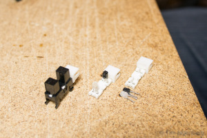
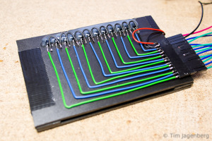
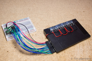
Using these components I build a new prototype, this time using contactless optical sensors. I drilled opposing holes into two plastic cards. On one side I glued the LEDs and on the other side the photo-transistors. The LEDs are powered by 3.3V chaining 3 LEDs serial and 4 groups parallel. The transistors use a common ground and are connected to the Teensy 3.1 inputs. The inputs have activated pull-up resistors, pulling them to 3.3V as well. With a free passage between the LED and the transistor, the light activates the transistor, which in turn pulls the input to ground. With the card in between, the transistor receives no light and let’s the input be pulled up to 3.3V. Thus the input pins follow an inverted logic.
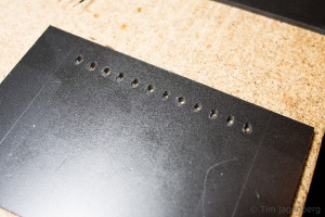
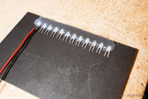
The two plastic plates are separated by two plastic guides to each side of the card. They provide guidance to the card when inserted, which is important for the correct hole alignment. As the optical card reader turned out to work rather reliable, I implemented a simple interpreter on the Teensy 3.1 which reads the card according to the IBM model 029 keypunch from the 60’s / 70’s. The micro-controller is recognised as a USB HID keyboard and sends the decoded characters as key presses. Each card is finalised with an ‘enter’ key press. The only adjustments I made are to only use every second column of the card in order to make sure all contacts close after each character. Also I added a space character encoding (Y&X row). You can download the binary and source code for the Teensy 3.1 based decoder from github.
Now all that’s left is to do is to use this device and send a ‘HELLO WORLD!’ tweet directly from punch card 🙂


