
Today I received the ESP8266EX Serial -> WiFi modules! After not being convinced by the rather expensive Adafruit TI CC3000 (35USD!) module I am now very curious about these tiny and cheap (<4USD) modules.
As their default header (2X4 male) is not exactly breadboard friendly, I sat down today and soldered a simple breadboard adapter. All you need is a tiny piece of stripboard 4×4, two male headers 1×4, two female headers 1×4 or one female header 2×4, and a bit of hot glue.
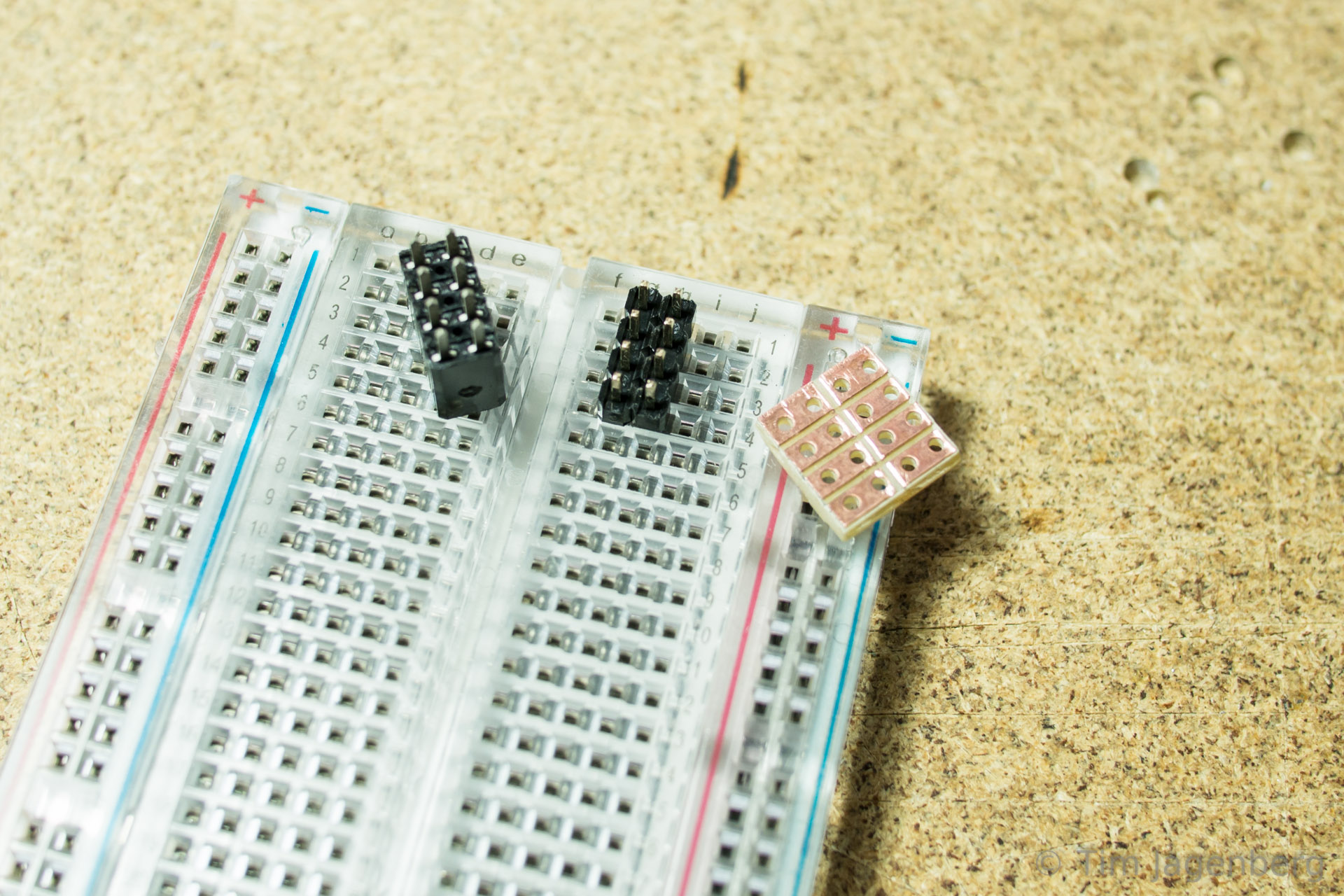


- Cut the stripboard to the correct size (4×4) and sandpaper any rough edges. Use a file to separate the copper strips across the middle.
- Place the female header on a breadboard using the male headers to give it some stability and solder it to the stripboard. Watch out for the correct orientation!

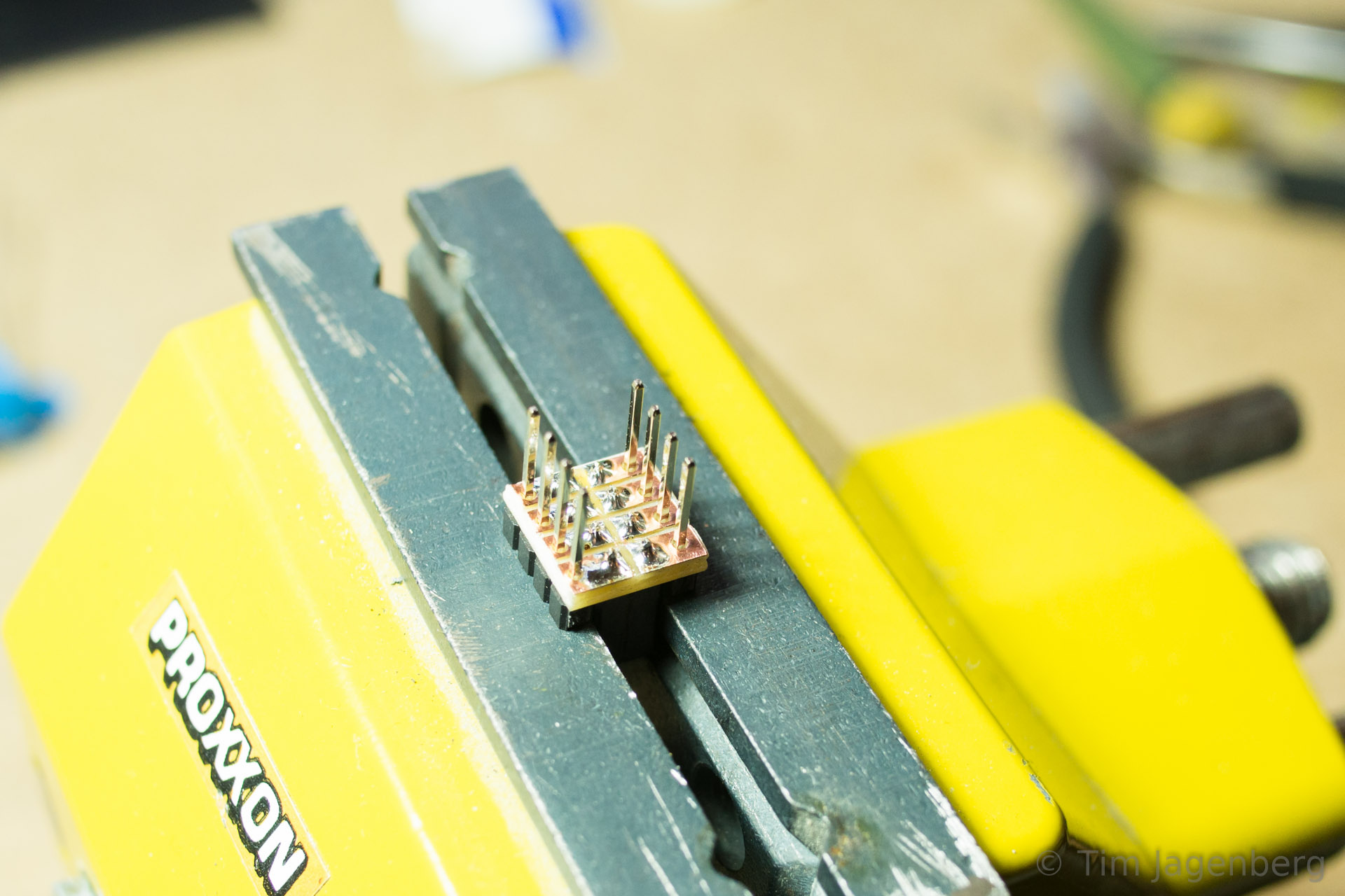

- Re-align the plastic spacer of the male headers all the way to the top.
- Place the stripboard with the male headers inserted from the non-copper side on some support (I used my vice for this).
- Solder the male headers to the stripboard.


- Now replace the plastic spacer of the male headers to the bottom side and push it as far up as possible (it probably will not go all the way because of the solder)
- Add some hot glue around the tips of the male headers to provide additional support and strength.
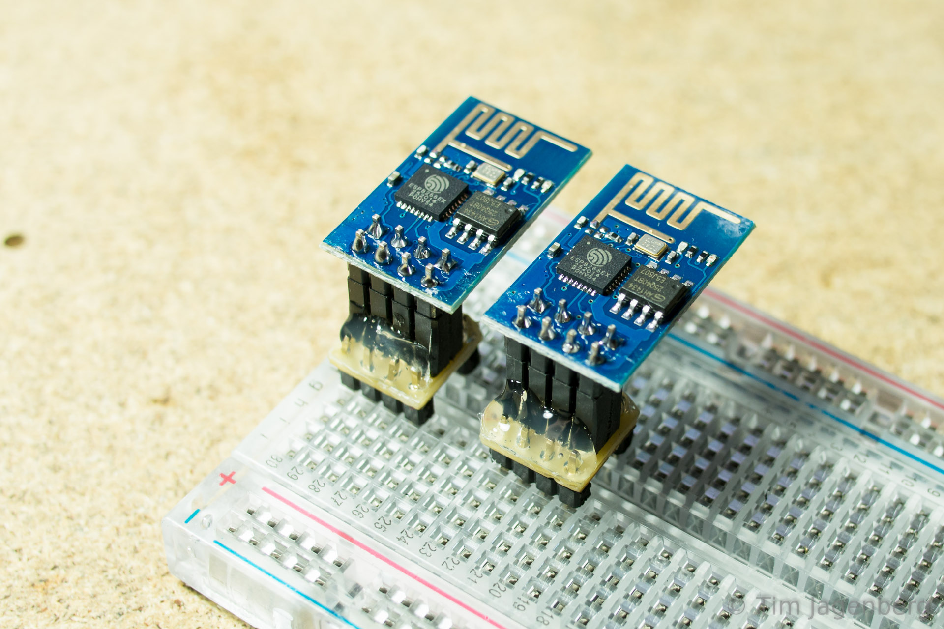
- Voilà!
The first tests using the Bus Pirate as UART bridge worked fine. I could talk to the module and connect to my home WiFi via WPA2.